..:: Parsethylene kish co. does not have any representative in iran ,The Company`s products are sold only through the central office with an official Certificate ::..

pipe installation

Pipe installation

Trenchless Piping

In recent years there have been large advances in trenchless technology for pipe installation and more can be expected in the next few years. In addition to tunnelling, there are four other methods of trenchless technology used for new pipelines in New Zealand.These are:

• Horizontal boring

• Directional Drilling

• Pipe Jacking

• Micro Tunnelling

The limits and advantages of each of the technologies are discussed below. This is intended as a general guideline only as rapid advances are being made and some equipment and some contractors may be able to obtain more distance or better accuracy.

Horizontal Boring

This is boring with normal drill rods in a horizontal (and hopefully straight) direction. A drill bed is up at the correct depth and aligned at the required direction and grade and a small hole drilled (typically about 70mm diameter). This hole is later reamed out to the required diameter. This can be done either with a cutter that back cuts a short length of the line and then pushes the cut material to the far end of the hole for removal or by pulling a pig or similar through the hole to expand the hole to the required diameter. This method can be used with pipelines up to about 900mm diameter or larger provided the ground conditions are suitable, and holes will remain open safely.

Advantages

The advantage with this method is that the drilling equipment is relatively cheap and it can drill rock if required. It can also be usedpipe installation at any depth. Over short distances relatively accurate line and grade bores can be achieved. Claims of accurate grades of 0.5% over 30 – 50 m are common in the industry. My personal experience is that this is generally not obtained and that to get 0.5% lengths have to be less than 30m.

Disadvantages

The disadvantages are that the drill head cannot be controlled after drilling starts. The head generally slowly falls below the grade that it started at. It can however go in any direction if a hard layer is encountered at a shallow angle to the bore direction. Because of the tendency of the drill to slowly fall off the design grade a maximum length of about 60m is recommended for firm consistent materials. In hard materials where the drilling head is likely to be deflected by varying strengths of materials and in soft materials where it is likely to “fall” more rapidly this distance may have to be reduced to as little as 10m.

A drilling pit is required to the depth of the line and in the location of the line. The pit has to be long enough to fit the machine in. This is generally not a problem but can be on some confined sites.

As the original hole is reamed out after drilling the final hole can at times finish up with it’s centre not in the same location as the original and some variation additional to that caused by inaccuracies in the original drilled hole can occur.

Pipe Materials

With this method polyethylene pipes would be the most common material. However, concrete, steel, PVC or Hobas GRP can all be used. With these materials the pipe jointing needs to be considered. Rubber ring joint pipe should not be used as the installation will push the joints in past the witness marks causing failure of the pipe collars. If the pipe is not the same outside diameter over its full-length consideration needs to be made of if and how the annulus between the drilled hole and the pipe is to be filled.

Directional Drilling

In Directional Drilling drilling the initial pilot hole can be steered (within limits). Directional drilling typically starts from the surface some distance away from the start of the permanent line and drills down and onto the required line and grade. The driller can control the direpipe installationction of the drill head both vertically and horizontally. The drill head position is monitored from the surface where both it’s position, depth and inclination can be measured. If it is not in the correct position a correction can be made to the drilling direction. Normally a pilot hole is first drilled and is subsequently reamed or pigged out.

This system is becoming increasingly common especially for telecom ducting and gas mains. Many watermains and sewers are now being installed with this method. It is suitable for pipelines up to about 900mm diameter, and ranges up to 500 metres or more, depending on depth and ground conditions.

The accuracy of this method is largely dependant on the skill of pipe installationthe operator and the accuracy of the location equipment used to locate the drilling head. Most equipment in New Zealand is described as accurate to 1% (or a similar figure). When directional drilling equipment is described in this way, it is important to understand that this is NOT the gradient standard achievable for the final pipeline. It is the accuracy to which the position of the underground drill head can be determined at any given time, during the drilling operation. All machines are less accurate in the horizontal direction than in the vertical direction.

At least one 0.1% accuracy machine is now in New Zealand. I have not seen the results of this machine but I would expect that it should be able to drill to grade of about 1% at depths of up to 3 to 4m but some horizontal weaving would be expected.

Advantages

Many contractors have directional drilling equipment. It is relatively cheap and quick to install. Most soil materials can be handled provided they are reasonably consistent. With suitable drilling muds, pipelines can even be installed in running sands below ground water level.

Disadvantages

It has the disadvantage that the drilling head has to be off alignment before action is taken to correct it. There are also limitations with the accuracy of the detection equipment that is used to locate the drilling head. Most surface directional boring detection equipment becomes unreliable or does not record at all below about 3.5m although some claim to be able to operate at 5 to 6m. The final drilled hole is generally not very straight. At times this is improved when the hole is reamed as this can straighten out some of the wandering. With increasing accuracy of machines these limitations are decreasing.

The major risk is associated with inconsistent soil conditions where for example, interfaces between soft and hard soils cause the line to deflect, or buried boulders, rocks, tree trunks and the like might bring the drill to a complete halt. The back-reaming cutter is also selected depending on the material, so a clay cutter is unsuitable for back-cutting soft sandstone. This means it is often not feasible to drill from one type of soil into another of significantly different characteristic.

The other major aspect to consider is the space needed to lay out the pipe string before it is pulled into final position. Small diam pipes are quite flexible and can be threaded around surface obstructions, but as diameters increase this rapidly becomes more difficult.

Pipe Materials

Welded polyethylene pipes or PVC pipes with solvent cement or threaded joints may be used.

Pipe Jacking

With this method the pipe is pushed through the ground from a jacking pit. The material is excavated from inside the pipe and the pipeline advanced by pushing again. The line and grade can be controlled by the amount of excavation around the driving head. As the line advances new pipes are added at the start and jacked along the line.

Advantages

This method has the advantage that it can be used for large pipelines where the other methods discussed above are not suitable. This method has the advantage that good control of direction and grade is possible with a good contractor.

Disadvantages

Care is required in the design to ensure that the pipes have sufficient strength for the jacking forces required for installation. Typically special manufacture jacking grade pipes are used.

Simple “Pipe Jacking” is now generally considered to cover situations where excavation at the face is manually undertaken. This limits operation to pipelines with a minimum of about 1500mm diameter, but can offer a major advantage in that there is no large tunnelling machine that must be extracted once the end of the jacked pipeline is reached.

The method is not suitable for lines in running sands. The method is generally very expensive, but for large diameter deep lines may be the only available option.

Pipe Materials

The pipe material must be strong enough to take the jacking forces required. Concrete is typically used, but earthenware, steel or fibreglass can also be used.

icro Tunnelling

Micro-Tunnelling is similar to Pipe Jacking but uses some form of mechanical excavation machine at the face. The machine can take several forms depending on ground conditions and how the spoil is removed. Two common styles are the “slurry” machine, whepipe installationre the spoil is turned into a watery slurry for removal, and the “partial open face “ machine where spoil in a relatively unchanged state is removed by skip, conveyor or auger.
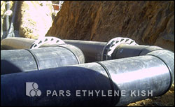
This system requires a pit to be excavated to the proposed pipeline depth. The pit has to be large enough to fit the boring machine and/or pipes and the hydraulic jacks. The size required varies from machine to machine. For the smaller machines this may be as little as 1.5m. For larger machines it may be 10m or more.

The drilling machine is located in front of the first permanent pipe. Normally the pipeline is steel or concrete but other materials may be used. A steel pipe can be used as a casing with the service pipe installed inside the steel duct later. The drilling machine is steered from a control panel at the surface using remote CCTV and laser guidance.

Depending of the type of machine numerous services such as power, hydraulics, water and lubricant may need to be fed to the tunnelling machine. These services must de disconnected and then reconnected each time a new pipe is added to the string. Significant equipment and space is also needed at the surface for lifting pipes into the pit, storage of pipes and so on. For slurry machines large screens and tanks are also required at the surface to settle the muck out.

The larger machines generally drill a full size hole. Some of the smaller machines drill only a small hole (approx. 70mm) which is later reamed out to the required size. At least three of these smaller machines are presently in NZ. These smaller machines have a maximum range between pits of about 70 to 100m. After this it is difficult to see the laser guidance dot on the target. Larger machines can often tunnel for a few hundred metres between pits. The governing factor is often the pipe resistance in the hole, although this can be eased by lubrication. As the pipeline gets longer the forces become greater and the pipes may crush. In this case drive lengths can be increased with the use of intermediate jacking points.

At present it appears that this technology is economic at depths greater than about 6m and when it is necessary to lay a line very close to or under existing buildings or services that cannot tolerate the disruption caused by open cut methods. It should nevertheless be recognised that substantial surface disruption cannot be totally eliminated, and in particular the disruption that does arise will remain in the same location for a considerable period.

Advantages

These machines give very accurate bores. They are however very expensive, although the price is coming down as more machines become available.

Slurry machines can cope with virtually any type of soil including running sands and soft rocks. Open face machines can only cope with soils that are reasonably self-supporting, but require far less surface spoil processing equipment.

Disadvantages

The technology is relatively expensive and there are limited contractors with the equipment in New Zealand.

Pipe Materials

Pipe jacking pipes are usually earthenware and concrete but steel and Hobas-fibreglass are also used.

Source: New Zealand Water


Valve | PEX pipe | Push fit system | Plastic pipe | HDPE pipe | Water pipe

UPVC pipe | Spiral pipe | Gas pipe | Underground pipe | Polyethylene pipe fitting | Pipe installation

 OHSAS 18001  ISO 14001  ISO 9001

PE Pipe

Polyethylene Pipe (PE80 - PE100)

PE Fitting

Polyethylene Fitting

PE Manhole

Polyethylene Manhole

PE Welding

Polyethylene Welding Machine


Top categories

UAE 1: 00971 56 286 1414
H.Emami @ Parsethylene-kish.com
UAE 2: 00971 56 286 1515
Info @ Parsethylene-kish.com
IR : +9821 88 20 20 60
  Contact us
  Pars Ethylene Kish at a glance
  Pars Ethylene Kish, a symbol of capability and quality
  Mission and Vision
  Sale and its Strategies in Pars Ethylene Kish
  Reason for High Quality of Pars Ethylene Kish Products
  Quality Control Laboratory
  Guaranty & after sales service
  Reasons of paying attention to quality
  INSO Certificate
  Maintenance and storage of HDPE pipes
  Instructions for storing HDPE pipe against UV
  Polyethylene Joining Procedures
  Polyethylene Pipe
  HDPE pipes for gas supply
  HDPE Corrugated Pipes
  HDPE Single Wall Fittings
  HDPE Double Wall Fittings
  HDPE Electrofusion Fittings
  Cage fish farming
  Domestic Sewage Treatment
  Polyethylene Manholes
  Telecommunication manhole
  HDPE Fire Fighting Pipe
  HandBook of HDPE Pipe
  HDPE Pipe price list
  Price list of double-Layer Corrugated pipe
  FM Approval
  PDMS Catalogue
  HDPE Pipes in Power Plants
  HDPE Pipes in railway and urban rail
  HDPE Pipe in Mining
  HDPE Pipe in Airport
  HDPE Pipe in Conducting Agricultural Pesticides
  HDPE Pipe in drain
  HDPE Pipe in Landfills
  The Coating Materials Of Steel Pipes
  Cable Covering
  HDPE pipe in Ventilation
  HDPE Pipe in Ships
  HDPE Pipes in Floor Heating
  Gallery
  Polyethylene Manhole Sewage
  U-PVC Pipe
  Draining Pipe
  PEX Pipe
  Polyethylene drip irrigation tape
  PushFit System
  HDPE Dredging Pipe
  Polyethylene Welding
  Sewer Fittings
  Application of Polyethylene Manhole
  Polyethylene Tank
  PE Septic Tank
  PE Jersy Barrier
  Fire Sprinklers
  Composite Manhole Cover
  PE Valve Box
  HDPE Pipe in Sea Water
  Price of HDPE pipe
  Brochures & Catalogue
  Polyethylene Machinary
  Certificates
  Raw Material
  Borouge HDPE Pipe Systems
  Reference standards
  Standards for HDPE Pipe
  Technical Data
  Job Opportunities
  HSE Plan
  Welding Course Study
Quality Begins with Pars Ethylene Kish The new generation of parsethylene kish corrugated pipes PDMS Catalog Pars Ethylene Kish Polyethylene cage fish farming Domestic Sewage Treatment FM Approval Certificate Pars Ethylene Kish Isiri Certeficate of Parsethylene Kish 17025 Certificates Integrated Management System SGS Quality Managment System Raw Material of HDPE of Parsethylene Kish Reference standards of Polyethylene, PVC and polymer Handbook of Pars Ethylene Kish products Technical Certificate of Road, Housing and Urban Development Research Center Health Premission of Polyethylene pipefor water supply New Generation of Composite Cover Failure modes and mechanisms in cast iron pipe Case Studies Reference standards of PE, PVC and polymer Fun & Game Join us on FaceBook Follow Us on Telegram

Pars Ethylene kish does not have any representative in iran ,The Company`s products are sold only through the central office 

::
Copyright © 2007- 2018 Pars Ethylene Kish Co. :: All rights reserved :: Design & Development by: Pars Ethylene Kish ::