|

The Evaluation of Failure of Plastic Pipes Used for Potable Water Transfer
Introduction
Potable water disinfection by chlorine or chlorine dioxide can negatively affect the longevity of plastic pipes. In this paper failure in the plastic pipes for potable water transfer and impact of failure and affects of oxidation or mechanical factors that cause or spread the failure of these pipes are investigated.
The use of plastic pipe for fluid transfer began in 1940. Increasing use of these 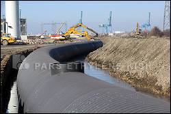 pipes, various test methods also to predict long-term resistance has spread further and gained importance. The tests proposed by these methods were led to the identification of three types of failure in plastic pipe. pipes, various test methods also to predict long-term resistance has spread further and gained importance. The tests proposed by these methods were led to the identification of three types of failure in plastic pipe.
• The first type of failure: tough failures affected by mechanical factors
• The second type of failure: fragile failures affected by mechanical factors
• The third type of failure: fragile failures affected by oxidation factors
Gradually and according to the test methods, standards such as ASTM D 2837 and ISO 9080 have been provided to investigate the mechanical performance of plastic pipes especially in the first and second types of plastic failure.
In the third type of failure, performance of pipes not only is dependent on mechanical strength but also resistance of plastic materials against oxidative substances. Be exposure to different environments can accelerate oxidative degradation process and thus reduce the longevity of 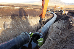 the pipe. As mentioned earlier, the presence of disinfectants such as chlorine or chlorine dioxide accelerate this type of failure. In order to investigate these types of failures test method under standard ASTM 2023 F to determine the resistance of networked polyethylene pipes (PEX) is defined against the oxidation factor. the pipe. As mentioned earlier, the presence of disinfectants such as chlorine or chlorine dioxide accelerate this type of failure. In order to investigate these types of failures test method under standard ASTM 2023 F to determine the resistance of networked polyethylene pipes (PEX) is defined against the oxidation factor.
It should be considered other polyolefin pipes such as polyethylene are also used to potable water transfer, but due to relatively low operational temperatures oxidative factor is not a criterion to determining the amount of resistance of polyolefin pipes used in potable water transfer.
It is assumed that the failure of other types of polyolefin pipes is somewhat similar PEX pipes, although some accelerator tests fails this issue and have concluded that in the other polyolefin pipes the failure not unique to three types of failure previously mentioned and the second and third types of f are separately divided to four following modes:
• Mode 1: Creation and propagation of cracks by mechanical factors
• Mode 2: Creation of cracks by mechanical factors, and then extend it by  oxidative factors oxidative factors
• Mode 3: Creation of cracks by oxidative agents and then spread it by mechanical factors
• Mode 4: Creation and propagation of cracks by oxidative factors
Modes 1 and 4 are of common and standard failures of second and third type, respectively. In the case of 2 and 3 modes, creation and propagation of cracks is not the usual type of failures. In the failure mode 2 although initial treatment of pipe is similar to standard failure the second type but the continued propagation of cracks depends on the oxidation resistance of the pipe and in the failure mode 3 creation of cracks in reverse of mode 2, depends on oxidation resistance of ingredients of pipe. It means immediately after cracking by oxidative agents, its expansion is not function of this factor and is dependent on mechanical factors.
In this paper tried to examine the examples of failures in polyolefin pipe and compared to four failure modes.
Tests
In many instances of polyolefin pipes that have failed, fragile failure is observed. These failures during the reviews are performed in the services, are detectable. The tests commonly used for this type of failures are microscopic review of internal and external surfaces of cracks, test to determine the oxidation induction time (OIT) under standards 11357-6-ISO 2002 in temperature of 200 ° C on the inner layer and mid wall of tube and MICRO-ATR test to examine the internal and external levels of crack.
 Test Results Test Results
Visual and microscopic examination of crack:
Sample examination on sample of tubes that have failed indicates the fact that the failure rate of the internal surfaces of the tube is different together. The amount and number of microscopic cracks of the internal surfaces is different from another example. The complementary test to this method is reverse bending test that determines how much damage. Figures 1 and 2 show the inside surfaces of three test samples before and after the bending test reverse.
Before testing, creation small minor cracks on the surface that there is no crack on it can be seen. While after the reverse bending test, minor cracks generated on the interior surface of the pipe disconnected and cracks became bigger (Figures 2b, 2a and 2c).
Studding the fracture level on the samples can be concluded that in almost all cases the failure factor is slow growth of cracks and second type of failure that is fragile fracture affected by mechanical factors. In other words, the created ring affected by the slow crack growth in most of these samples is evident. (Figure 3)
 2- OIT Test 2- OIT Test
Table 1 show results of OIT test on samples taken from the internal surface and mid wall of rejected pipe. Based on these results OIT rates are low and it indicates that stabilizer don’t remain on inner surface of pipe. Yet OIT test rate that are made of mid wall of pipes are more than internal surface.
3- FTIR Test
FTIR test on samples are prepared of internal surface, mid wall center (from part that has less distance of cracked surface) and surface inside and front, is done (Figure 4). Figure 5 shows a diagram of FTIR test are prepared of inner surface of the pipe. The ratios of carbonyl that are level of between degradation are calculated and presented in Table 2. Based on the above table, the highest amount of damage occurring in the inner pipe as we get closer to out and surface of the pipe, the degradation reduced and in areas away from the crack and on the crack the least amount of damage or lack of damage is observed.
 Evaluation of Test Results: Evaluation of Test Results:
In general, the following features are observed in rejected samples:
• There is damage to the inner surface of the pipes according to the results of microscopic observation of very small cracks, low OIT and the ratio of carbonyl FTIR test
• The difference in the rate of degradation of surface cracks in the test. While in all cases whatever gets closer to the outer surface of the crack the damage reduced.
• Failure to observe the destruction on the crack surface
• Failure surface almost at all instances with slow growth features of crack is similar.
Failure to destruction on inner visible layers that have tiny cracks also lower amount of damage on the crack might indicate that the failure of third kind that is the fragile fracture is not affected by oxidative factor. Conversely, damaged surfaces that can be observed by FTIR tests and reverse bending also noted that the failure can be failure of the second kind (fragile failure are affected by mechanical factors).
 Based on this observation, it can be concluded that these failures of the third mode of failure caused by the failure of oxidative agents and then spread by mechanical factors. Although the rate of degradation of the sample due to slight differences in raw materials used in the zmanufacture of pipes will differ and the amount of damage and the number of microscopic cracks, especially depends on the amount of stabilizer and material resistance and crack slow growth. So the failure mode 3 is dependent on the oxidative stability of raw material of pipe and its resistance against crack slow growth. In fact, this type of failure is a combination of the failure of the second and third type. Based on this observation, it can be concluded that these failures of the third mode of failure caused by the failure of oxidative agents and then spread by mechanical factors. Although the rate of degradation of the sample due to slight differences in raw materials used in the zmanufacture of pipes will differ and the amount of damage and the number of microscopic cracks, especially depends on the amount of stabilizer and material resistance and crack slow growth. So the failure mode 3 is dependent on the oxidative stability of raw material of pipe and its resistance against crack slow growth. In fact, this type of failure is a combination of the failure of the second and third type.
According to given figures many examples of such as C, it can not be classified in row 3 mode failures. Since the reverse bending test is performed on these samples can not shows notable destroyed or tiny cracks on the inner surface of pipe. Also on crack surface at least destruction can be seen. Study crack is to point out that the samples, particularly due to the external load of soil and rock during the service operation the second type of failure has been occurred.
 Comparison of Experimental Failures Comparison of Experimental Failures
in the figures 6 and 7, failures of the experimental samples produced of polyolefin are shown. These samples based on 2263 ASTM F standards were tested. Figure 6 show
the inner surface of the sample is free of any cracks after reverse bending test gradually cracks are formed on the inner surface. Cracks on the surface have characteristics of crack slow growth in the second kind of failure. Accordingly, it can be claimed that the failure in the experimental samples, is the fracture mode 3.
Conclusions
the study of failure in polyolefin indicates that transfer potable water through these pipes can lead to failure mode 3 in the pipeline. Experimental testing proves that the test method presented in the Standard 2263 ASTM F is a valid method for strength of polyolefin pipes against potable water disinfectants and thus estimate the lifetime of the pipes.
Table 1: OIT Test Results

Table 2: FTIR Test Results

Figure 1: The inner surface of the failed sample before the reverse bending test 
Figure 2: The inner surface of the failed sample after the reverse bending test

Figure 3: Cracks surface (ID inner surface and OD outer surface) 
Figure 4: Example of FTIR regions

Figure5: FTIR Sample A

Figure 6: Cracks surface of a refused experimental sample before and after the reverse bending test

Figure 7: Cracks surface of a refused experimental sample 
References:
1. K. Oliphant, S. Mruk, Forecasting the Long-Term Strength of Thermoplastic Piping
Materials – A Review of the History, Current Status and Proposed Refinements to the Generally Accepted Knowledge, presented at the American Gas Association Symposium, San Francisco (2002).
2. ASTM D2837 Standard Test Method for Obtaining Hydrostatic Design Basis for
Thermoplastic Pipe Materials or Pressure Design Basis for Thermoplastic Pipe Products, ASTM International, USA (2004).
3. ISO 9080 Plastics piping and ducting systems – Determination of the long-term hydrostatic strength of thermoplastics materials in pipe form by extrapolation, ISO, Switzerland (2003).
4. ASTM F2023 Standard Test Method for Evaluating the Oxidation Resistance of Cross linked Polyethylene (PEX) Tubing and Systems to Hot Chlorinated Water, ASTM International, USA (2005).
5. ASTM F2263 Standard Test Method for Evaluating the Oxidative Resistance of Polyethylene (PE) Pipe to Chlorinated Water, ASTM International, USA (2005).
6. S. Chung, J.D. Kim, M. Toro, P. Vibien and K. Oliphant, Modeling Mechanisms of Brittle Oxidative Degradation to Ensure Plastic Pipe Material Performance, ANTEC, Chicago (2004).
7. S. Chung, K. Oliphant, P. Vibien and J. Zhang, An Examination of the Relative Impact of Common Potable Water Disinfectants (Chlorine, Chloramines and Chlorine Dioxide) on Plastic Piping System Components, PPXIII, Washington D.C. (2006).
8. ISO 6 -11357 Differential Scanning Calorimetry (DSC) – Part 6: Determination of Oxidation Induction Time,
Source: Translated From Baspar Magazine - Omid Kooshki
PE Welding
PE Manhole
PE Fitting
PE Pipe
Valve | PEX pipe | Push fit system | Plastic pipe | Polyethylene pipe
Water pipe | HDPE Pipe | Corrugated pipe | Spiral Pipe | PVC Pipe | Sewerage pipe
|